


How Does a Soldering Heating Element Improve Temperature Stability?
Summary: If your solder joints look dull, your tips burn out too fast, or your station feels “hot but not effective,” the culprit is often not your technique—it’s heat transfer and recovery. This article explains what a Soldering Heating Element actually does, why temperature stability fails in real production, and how to choose, maintain, and troubleshoot a heater so you get consistent solder flow, fewer defects, and less downtime.
Table of Contents
- Outline at a Glance
- What Is a Soldering Heating Element in Practical Terms?
- Common Customer Pain Points and What They Really Mean
- Why Temperature Stability Fails
- Heater Types and When Each Makes Sense
- Selection Checklist for Reliable Results
- Comparison Table
- Maintenance and Tip-Life Best Practices
- Troubleshooting: Symptoms, Causes, Fixes
- Working with a Manufacturer for Custom Heating Performance
- FAQ
Outline at a Glance
- Define what the Soldering Heating Element is and what it controls (not just “heat,” but recovery and transfer).
- Translate real shop-floor complaints into measurable heater issues.
- Explain stability killers: sensor placement, thermal coupling, power density, oxidation, and control lag.
- Compare heater technologies and match them to applications.
- Provide a practical selection checklist and maintenance playbook.
- Offer troubleshooting steps that reduce scrap and rework.
What Is a Soldering Heating Element in Practical Terms?
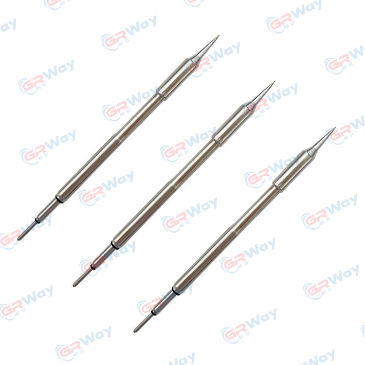
A Soldering Heating Element is the component that converts electrical power into controlled thermal energy at the point where solder must melt and wet the metal surfaces. That definition sounds obvious—until you notice that many soldering problems happen even when a station “reads” the correct temperature.
In practice, a heater’s job is not only to reach a setpoint; it must also recover instantly when heat is pulled away by a copper plane, a connector shell, or a thick lead. If the heater can’t keep up, you see symptoms like cold joints, prolonged dwell time, lifted pads, scorched flux, and tips that oxidize faster than they should.
Think of it like this: your controller can command “350°C,” but the joint cares about how quickly your system can deliver energy and keep the tip stable under load. That’s where heater design—materials, geometry, sensor coupling, and insulation—makes or breaks the experience.
Common Customer Pain Points and What They Really Mean
If you’ve said any of these, you’re not alone:
- “It heats up, but it struggles on big joints.” Usually low recovery power, poor thermal coupling, or sensor lag.
- “My tips wear out too quickly.” Often excessive dwell time, overheating cycles, oxidation, or incompatible tip/heater fit.
- “Temperature swings when I touch the joint.” Limited power density or slow control loop response.
- “I’m getting inconsistent wetting.” Uneven heat distribution, oxidation, or unstable tip temperature.
- “We keep replacing heaters.” Thermal shock, insulation breakdown, mechanical stress, or contamination.
The key insight: most complaints are not “operator errors.” They’re system-level heat-transfer issues—meaning the heater, the tip interface, and the control method must be evaluated together.
Why Temperature Stability Fails
Temperature stability is a promise made by the entire soldering system. A strong Soldering Heating Element helps, but stability can still fail when any of the following are off:
-
Sensor placement is too far from the working surface.
If the temperature sensor (often a thermocouple or thermistor) is not closely coupled to the tip area, the station “thinks” it’s stable while the tip is actually cooling under load. -
Poor thermal coupling between heater and tip.
Tiny air gaps, loose fits, or wear can turn the interface into an insulator. The heater runs hotter to compensate, which accelerates oxidation and shortens tip life. -
Power density is mismatched to the job.
Fine-pitch work benefits from fast, controlled energy with minimal overshoot; heavy copper and shields require higher recovery capacity. A one-size heater often disappoints in mixed workloads. -
Insulation and lead design aren’t robust.
Repeated heat cycling stresses internal joints and insulation. If the heater is frequently bumped, twisted, or exposed to flux fumes, durability matters. -
Control behavior causes overshoot/undershoot.
Even a good heater can behave poorly with unstable control tuning. Overshoot burns flux; undershoot forces longer dwell time—both increase defects.
Heater Types and When Each Makes Sense
While branding varies, most Soldering Heating Element designs fall into a few technical families. Knowing the tradeoffs helps you avoid paying for the wrong “upgrade.”
-
Wire-wound ceramic heaters
Nichrome or similar resistance wire embedded around/within ceramic. Often cost-effective and widely used, with decent durability when well-made. -
Cartridge-style heaters
Compact heaters built into a tube form factor. They can deliver solid power density and can be designed for strong coupling to the tip structure. -
Integrated heater + sensor assemblies
Designs that place heating and sensing closer to the working surface. These often improve response time and reduce the “reading vs reality” gap. -
Self-regulating ceramic (PTC-like behavior)
Certain ceramics increase resistance as temperature rises, offering a natural limiting effect. Useful for some applications, though performance depends heavily on the full system design.
Practical tip: If you alternate between small components and heavy copper, prioritize fast recovery and close sensor coupling over “maximum wattage” alone. A stable 70W system can outperform a sloppy 120W system.
Selection Checklist for Reliable Results
Use this checklist when evaluating a Soldering Heating Element for a new tool, a repair program, or a production line:
- Recovery requirement: What’s the biggest thermal load you must solder (ground planes, shields, lugs, connectors)?
- Thermal coupling: How tightly and consistently does the heater interface with the tip or working surface?
- Sensor integration: Is the temperature sensor close enough to control the real tip temperature under load?
- Stability under airflow: Will fans, fume extraction, or drafts affect tip temperature?
- Electrical compatibility: Voltage, resistance range, connector type, and controller support.
- Durability factors: Thermal cycling life, mechanical robustness, insulation resistance, and lead strain relief.
- Serviceability: Can you replace the heater without reworking the entire handle assembly?
- Process fit: Does the heater support your solder alloy and flux strategy without forcing extreme setpoints?
Comparison Table
| Heater Approach | Best For | Strength | Watch-Out |
|---|---|---|---|
| Wire-wound ceramic | General soldering, balanced cost/performance | Reliable and widely supported | Performance depends heavily on coupling and control tuning |
| Cartridge-style heater | Higher thermal load, faster response needs | Good power density and consistent geometry | Fit/assembly quality is crucial to avoid air gaps |
| Integrated heater + sensor | Precision work, stable production processes | Improves stability and recovery at the tip | May require compatible controllers and specific tips |
| Self-regulating ceramic behavior | Controlled heat limiting for certain designs | Can reduce runaway overheating | Not a substitute for proper sensing, coupling, and process control |
Maintenance and Tip-Life Best Practices
Even the best Soldering Heating Element will feel “weak” if the tip is neglected or the process is inconsistent. These habits reduce oxidation, improve wetting, and protect the heater assembly:
- Use the lowest effective setpoint. Higher temperature is not “more professional.” It often just burns flux faster.
- Keep the tip tinned. A thin solder coat reduces oxidation and improves heat transfer to the joint.
- Match tip geometry to the joint. A tip that contacts more surface area transfers heat faster, reducing dwell time.
- Limit dry wiping and abrasive cleaning. Over-cleaning damages plating and accelerates tip failure.
- Protect leads and strain relief. Many heater failures begin as mechanical failures, not thermal ones.
Quick reality check: If you’re compensating for poor recovery by holding the iron on the joint longer, you’re increasing pad damage risk and raising the total heat exposure of the assembly. A better heater setup usually reduces total thermal stress.
Troubleshooting: Symptoms, Causes, Fixes
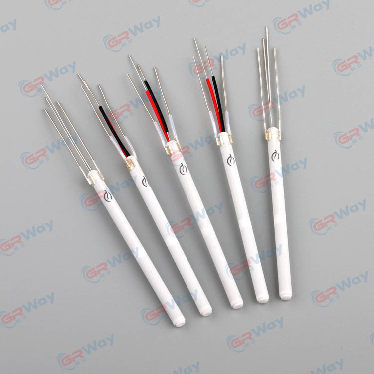
When soldering quality suddenly drops, you want a fast diagnosis—not guesswork. Here are common “symptom-to-fix” paths:
-
Symptom: Solder melts slowly on large joints.
Likely cause: Inadequate recovery, poor tip contact, or incorrect tip size.
Fix: Use a larger tip geometry, verify tight heater-to-tip fit, and confirm your controller isn’t limiting power. -
Symptom: Tip oxidizes rapidly, solder won’t wet.
Likely cause: Excessive setpoint, long idle time at high temp, or contaminated tip surface.
Fix: Lower temperature, use standby/sleep when possible, retin the tip properly, and evaluate flux compatibility. -
Symptom: Station shows stable temperature but joints look inconsistent.
Likely cause: Sensor is not reading true tip temperature under load, or there is an air gap at the interface.
Fix: Inspect heater seating, replace worn sleeves/retainers, and consider an assembly with closer sensor coupling. -
Symptom: Heater fails repeatedly after short use.
Likely cause: Thermal shock, mechanical strain, or insulation breakdown due to contamination.
Fix: Improve strain relief handling, avoid abrupt cooling (especially with aggressive airflow), and keep flux residue away from heater internals.
Working with a Manufacturer for Custom Heating Performance
If you’re sourcing heaters for a product line, servicing a fleet of tools, or scaling a production process, the best results often come from treating the heater as a designed component—not a generic spare part. A capable manufacturer can help you define targets like warm-up time, recovery behavior, operating voltage, sensor style, connector format, and thermal cycling life.
For example, Xiamen Green Way Electronic Technology Co., Ltd. can be approached as a technical partner when your application needs consistent heating behavior, stable assembly tolerances, and repeatable performance across batches. The goal is straightforward: ensure your Soldering Heating Element behaves the same way on day one and day one hundred—so your process stays predictable.
When you share your real use conditions (duty cycle, target materials, airflow, tip style, and peak load joints), it becomes much easier to avoid underpowered designs and prevent overshoot-prone setups that quietly damage boards.
FAQ
Q: How many times should I mention “Soldering Heating Element” in a product-focused article?
A: Use it naturally where it adds clarity—definition, selection, maintenance, troubleshooting, and conclusion. Clarity matters more than repetition, but keeping the phrase present in key sections helps readers understand exactly what component you’re addressing.
Q: Is higher wattage always better for difficult joints?
A: Not always. Higher power helps only if heat can transfer efficiently. Poor coupling, wrong tip geometry, or slow sensing can waste wattage and still produce unstable results.
Q: Why does my station overshoot and burn flux even at a “normal” setpoint?
A: Overshoot can come from aggressive control behavior, delayed sensing, or a heater design that stores too much heat relative to the tip. Adjusting control response and improving sensor coupling usually helps.
Q: What’s the fastest way to improve soldering consistency without changing the whole station?
A: Start with tip geometry and interface fit. A well-matched tip and snug heater seating often improve recovery and wetting more than a higher setpoint does.
Q: When should I replace the heating element instead of just the tip?
A: If warm-up becomes noticeably slower, recovery on large joints deteriorates, temperature swings increase, or the tool shows intermittent heating, the heater or its connections may be degrading.
Closing Thoughts
A stable Soldering Heating Element is the difference between “getting by” and running a process you can trust. When the heater is properly matched to your workload—and maintained with sensible tip practices—you reduce dwell time, cut defect rates, and protect both components and operators from unnecessary thermal stress.
If you’re evaluating a new heater design, planning a replacement program, or need a custom configuration for your soldering tools, reach out to Xiamen Green Way Electronic Technology Co., Ltd.—we can help you choose the right performance targets and production-ready specifications. Ready to reduce downtime and stabilize your soldering process? contact us to discuss your application.
Previous:ISO9001:2005
Send Inquiry





X
We use cookies to offer you a better browsing experience, analyze site traffic and personalize content. By using this site, you agree to our use of cookies.
Privacy Policy