


Choosing a Soldering Heating Element starts with understanding the actual soldering process rather than selecting a component by wattage alone. The required joint temperature, workpiece size, thermal load, supply voltage, physical dimensions, sensing method, and operating cycle all influence the suitability of a heating core. A considered selection process helps equipment designers identify compatible components, establish measurable performance requirements, and prevent avoidable problems during assembly and use.
This guide explains how to define application requirements, assess ceramic construction, compare electrical and mechanical specifications, evaluate temperature regulation, and verify a component before integration. It also covers common selection errors, inspection procedures, and practical questions about replacement and compatibility.
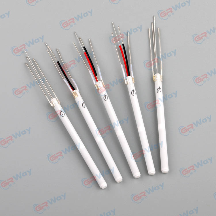
Table of Contents
Choose a topic below to jump directly to the relevant section.
- Define the Soldering Application First
- Determine the Actual Heat Requirement
- Match Voltage, Resistance, and Power
- Evaluate Ceramic Materials and Construction
- Confirm Dimensions and Electrical Connections
- Consider Temperature Sensing and Control
- Compare Specifications Without Guesswork
- Verify Performance Before Integration
- Avoid Common Selection Mistakes
- Frequently Asked Questions
- Final Technical Checklist
1. Define the Soldering Application First
The first decision is not which heater to purchase, but what the finished tool must accomplish. Two soldering tools may use ceramic heating technology while serving very different purposes. One may handle fine electronic connections, while another must transfer heat to larger terminals or conductors. Their thermal demands, tip structures, and control requirements can therefore differ substantially.
Identify the workpiece and joint characteristics
Begin by documenting the materials being joined, the approximate joint size, the shape of the contact area, and the amount of heat the workpiece absorbs. A small copper pad and a large metal terminal do not remove heat from the working tip at the same rate.
Workpiece thickness and thermal conductivity are particularly important. Materials that conduct heat away rapidly may require a tool with a different recovery profile from one used for small, thermally isolated connections. The heater should be evaluated alongside the intended tip geometry, since heat generation alone does not determine how effectively energy reaches the joint.
Describe the intended operating cycle
Consider whether the equipment operates intermittently or performs repeated soldering operations over an extended period. Record the expected startup frequency, typical heating duration, cooling intervals, and ambient conditions. These details help establish whether the design must prioritize rapid warm-up, temperature stability during sustained work, or recovery after repeated contact with a workpiece.
- Define the workpiece materials and the range of joint sizes.
- Identify the type of soldering tool and its intended operating environment.
- Estimate how frequently the tool heats, cools, and returns to operation.
- Specify the required temperature-control method and acceptable thermal variation.
- Record any restrictions on component size, weight, insulation, or lead routing.
A clear application brief gives the subsequent electrical and mechanical checks a practical purpose. Without it, a component may match a nominal rating yet perform poorly in the finished tool.
2. Determine the Actual Heat Requirement
Temperature requirements need to distinguish between the heater, the working tip, and the solder joint. These locations have different thermal conditions, so their temperatures should not be treated as identical.
The heater generates thermal energy, the tip transfers that energy, and the joint receives it while interacting with the workpiece and solder. Heat is also lost to surrounding components and the environment. The resulting temperature at the joint depends on the complete system rather than on the heater specification in isolation.
Separate the required setpoint from the component limit
The control setpoint describes the temperature that the equipment is intended to maintain at its designated measurement point. The permitted operating temperature of the heater defines a different limit. A manufacturing process such as ceramic sintering involves yet another temperature range and should not be used to infer the operating limit of a finished component.
Specify the normal working range, the required maximum operating condition, and the location where temperature must be measured. Also determine whether the application requires stable temperature during light contact, rapid recovery after a heat-intensive joint, or both.
Assess thermal response in context
Warm-up time measures how long the assembly takes to reach a defined temperature from a stated starting condition. Recovery time describes how the temperature responds after the tip loses heat during operation. These are related but different performance measures.
For example, a heater may reach its setpoint quickly when no workpiece is present but experience a substantial temperature drop when contacting a large metal terminal. This behavior may reflect the thermal load, tip design, contact quality, or control response rather than an inadequate maximum temperature rating.
Selection principle: Define the required temperature at a known measurement point and under a representative workload. A temperature figure without test conditions is not enough to compare complete soldering systems.
Consider both heat capacity and heat transfer
The energy required to raise a component's temperature depends partly on its mass and material properties. A larger tip or holder generally requires more energy to reach the same temperature change than a smaller part made of a comparable material.
However, reducing component size alone does not guarantee better performance. The design must still transfer useful heat to the joint, maintain adequate mechanical strength, and support the intended operating cycle. Select the heater and associated tip as a coordinated thermal assembly.
4. Evaluate Ceramic Materials and Construction
Ceramic heating technology is used in compact heating assemblies because the ceramic body can provide electrical insulation while supporting an integrated resistive heating structure. The final behavior depends on the material composition, heating-layer design, manufacturing process, dimensions, and quality of the finished component.
Understand alumina ceramic construction
Alumina, or aluminum oxide (Al₂O₃), is used in many electrical heating components. Its electrical insulation and thermal characteristics make it suitable for a range of compact heating designs. The exact properties of a finished part depend on the ceramic composition, processing conditions, geometry, and construction.
One manufacturing approach places a conductive resistive pattern onto ceramic material and integrates the layers through a controlled high-temperature sintering process. This structure can combine the heating circuit and insulating body in a compact assembly.
The product information associated with this ceramic heater range identifies 95% alumina as the main material and describes a printed heating layer integrated through high-temperature sintering. It also states that a heater surface can reach up to 800°C within 30 seconds. That figure should be checked against the specific model and its measurement conditions before it is used as a design or acceptance requirement.
Review the heating layer and insulation together
The resistive layer determines important electrical and heat-generating characteristics. Its pattern, dimensions, and relationship with the ceramic body influence resistance and heat distribution. Meanwhile, the insulating structure must meet the electrical requirements of the finished application.
Material selection alone does not prove that a particular component is appropriate. A ceramic grade, construction, and manufacturing process should be evaluated against the expected operating temperature, electrical stress, thermal cycling, and mechanical installation conditions.
Consider thermal and mechanical stress
Ceramic materials can offer useful high-temperature performance, but they may be vulnerable to impact, bending, and concentrated mechanical loads. A design should therefore avoid unnecessary stress on the heater during installation and operation.
Repeated heating and cooling can also affect the assembly. The ceramic body, resistive layer, connections, holder, and surrounding metal parts may respond differently to temperature changes. Their combined design must accommodate the intended operating cycle without relying on unverified assumptions about service life.
For product background, material information, and the manufacturer's stated scope, visit GREENWAY®.
5. Confirm Dimensions and Electrical Connections
Physical fit is as important as electrical compatibility. A heater that meets the required voltage and resistance may still be unsuitable if it cannot fit securely inside the handle, tip assembly, or surrounding holder.
Check the complete mechanical interface
Review the ceramic body's length and diameter, insertion depth, end geometry, lead exit position, insulation sleeve, and retaining arrangement. Measure the parts that determine alignment and contact, not just the overall external dimensions.
Clearance is important because the heater must fit without excessive force or unwanted movement. An overly tight installation may create mechanical stress, while an overly loose interface can reduce thermal contact or allow the component to shift during use.
Inspect lead wires and connection points
Lead material, length, routing, termination method, and insulation should suit the tool's electrical design. The leads must reach their connection points without excessive tension, sharp bending, or contact with surfaces outside their permitted temperature range.
Where multiple electrical circuits are present, distinguish the power connections from any sensor connections. Verify the pin arrangement against the relevant drawing instead of assuming that similar-looking parts share the same wiring configuration.
Confirm the interface with the working tip
The holder and tip arrangement provides the physical path through which heat reaches the workpiece. Contact conditions, insertion depth, surface condition, and component alignment can influence thermal resistance.
For a replacement, compare the original part number and technical drawing whenever possible. Similar appearance does not establish equivalent resistance, sensor behavior, insulation, or mechanical fit. A dimensional match alone is not sufficient grounds for substitution.
7. Compare Specifications Without Guesswork
A useful comparison sheet should distinguish confirmed specifications from values that remain undefined. This makes it easier to evaluate alternative models without assuming that similar product names or external dimensions mean equivalent performance.
| Evaluation Item | Information to Record | Reason for Verification |
|---|---|---|
| Application | Tool type, workpiece, typical joint size, operating cycle | Establishes the actual thermal demands. |
| Electrical rating | Rated voltage, nominal power, resistance, tolerance | Confirms compatibility with the power supply and drive circuit. |
| Temperature range | Required setpoint, permitted operating range, measurement point | Separates the application requirement from the component limit. |
| Thermal response | Warm-up time, recovery behavior, defined test conditions | Supports meaningful performance comparisons. |
| Mechanical dimensions | Length, diameter, end geometry, insertion depth, tolerances | Confirms the part fits the intended assembly. |
| Connections | Lead arrangement, wire type, termination, insulation | Reduces integration errors and unsuitable wiring changes. |
| Sensing and control | Sensor type, sensor position, controller compatibility | Supports accurate temperature feedback and regulation. |
| Quality verification | Inspection criteria, test method, acceptance limits | Defines how conformity will be assessed. |
Actual ratings, dimensional tolerances, and test limits should be confirmed in the technical documentation for the specific model under consideration.
Evaluate equivalent operating conditions
Comparing two components is only useful when their results are measured under consistent conditions. Starting temperature, power supply, controller settings, tip geometry, sensor location, and applied thermal load can all affect the outcome.
For example, a warm-up measurement taken at the ceramic surface should not be compared directly with a measurement taken at the working tip unless the test method establishes a valid basis for doing so. Similarly, an unloaded temperature test cannot fully describe recovery under repeated contact with a workpiece.
Use published specifications for initial screening, then apply a defined validation procedure to confirm suitability for the actual application.
8. Verify Performance Before Integration
Before a component is approved for production use, verify that its electrical, mechanical, and thermal behavior meets the design requirements. The precise procedure depends on the equipment, but a structured evaluation helps separate specification mismatches from assembly problems.
- Review the documentation: Confirm the component identification, electrical ratings, dimensions, connections, temperature limits, and sensor details.
- Inspect the physical condition: Check for visible cracks, damaged insulation, bent leads, contamination, or other defects that may affect installation or safety.
- Check electrical continuity: Use the specified measurement method to check the heating circuit and relevant connections. Compare the result with the model's rated resistance and permissible tolerance.
- Verify the assembled fit: Confirm alignment, retention, clearances, lead routing, and the intended contact between the heater and surrounding components.
- Conduct a controlled heating test: Use the approved supply, control settings, sensor arrangement, and temperature-measurement method.
- Evaluate the intended workload: Measure temperature behavior during representative soldering operations, including recovery after heat is transferred to the workpiece.
- Document the result: Record the test conditions, measurements, observed behavior, and compliance with defined acceptance criteria.
Use repeatable measurement methods
Temperature measurements can vary with instrument type, probe placement, contact pressure, and response time. Establish a consistent method before comparing components. If a measurement instrument has not been selected, determine the required measurement range, accuracy, and response characteristics for the test.
Electrical checks should also follow the relevant procedure. Resistance readings may differ with temperature and measurement conditions, so the component should be assessed against the correct reference conditions.
Separate heater defects from system problems
When an assembled tool fails to reach its required temperature, inspect the entire heating circuit rather than automatically attributing the issue to the core. Possible causes include an unsuitable power supply, loose connections, a mismatched sensor, incorrect controller settings, poor thermal contact, or an unsuitable tip.
This diagnostic approach helps identify the real problem and avoids replacing a compatible component when the fault lies elsewhere in the system.
9. Avoid Common Selection Mistakes
Choosing by power rating alone
Power is only one part of the specification. A component may have sufficient nominal wattage but still fail to deliver the required behavior because the tip, thermal interface, or controller is unsuitable. Compare thermal response and the complete system configuration as well as electrical ratings.
Confusing the heater temperature with the tip temperature
A heater's surface temperature does not necessarily equal the working-tip temperature, and neither necessarily equals the temperature at the solder joint. Always identify the measurement location and operating conditions associated with a stated temperature.
Assuming similar models are interchangeable
Components from different tool models may have similar shapes while differing in resistance, lead configuration, sensor characteristics, power requirements, or insulation. Confirm the specifications before approving a replacement.
Ignoring thermal contact
A heater may perform differently when placed inside a holder or tip assembly with poor contact. Examine the interface, insertion depth, alignment, and assembly tolerances before making changes to the electrical system.
Changing operating voltage to compensate for weak heating
Increasing supply voltage without checking the design can impose excessive electrical and thermal stress. Investigate the rated supply, circuit connections, control response, and heat-transfer path before changing any operating condition.
Accepting specifications without test conditions
A temperature or warm-up claim is difficult to interpret unless the starting condition, measurement point, supply conditions, and test method are known. Ask for the relevant model-specific details and establish measurable acceptance criteria for the finished tool.
10. Frequently Asked Questions
What information is needed to select the correct heater for a soldering tool?
Start with the tool model or assembly drawing, rated supply voltage, power requirements, heating resistance, physical dimensions, lead arrangement, sensor type, and required operating range. Information about the workpiece and typical operating cycle helps establish whether the thermal behavior is suitable for the intended application.
Is a higher-power heater always the better option?
No. Higher rated power may provide greater heating capacity, but it does not guarantee better temperature stability or recovery. The power supply, control circuit, thermal interface, tip geometry, and workload must all be compatible with the heater. Select according to the required performance rather than maximizing wattage.
Why do rated voltage and resistance both matter?
Voltage and resistance determine current and electrical power in a resistive circuit under defined conditions. A mismatch can lead to inadequate heating or excessive electrical stress. Both values should be checked against the component documentation and the actual power-control arrangement.
What does a ceramic heating structure offer?
A ceramic heating structure can combine a resistive layer with an electrically insulating body in a compact design. Its actual thermal response, insulation performance, and mechanical durability depend on the materials, construction, manufacturing process, and finished assembly. These characteristics should be verified for the specific component.
Can a replacement heater be selected using dimensions alone?
No. Dimensions establish only part of the mechanical fit. Voltage, resistance, power, sensor compatibility, lead configuration, insulation requirements, and operating limits must also match. Check the component documentation and confirm performance in the intended assembly.
How should warm-up time be compared between different models?
Use the same starting temperature, supply conditions, measurement location, controller settings, and defined target temperature. Also verify whether the stated time refers to the heater surface, tip, or another point. Consistent conditions are essential for a meaningful comparison.
What can cause inconsistent soldering temperature?
Potential causes include unstable power delivery, damaged connections, sensor problems, incompatible control settings, poor thermal contact, and an unsuitable tip for the workload. Inspect the whole assembly and test under repeatable conditions before deciding that the heater itself has failed.
How can the quality of an incoming heating component be checked?
Follow documented acceptance criteria covering identification, visible condition, dimensions, electrical characteristics, connections, and applicable insulation requirements. Where appropriate, conduct a controlled functional test in a compatible assembly. Record test conditions and results so that conformity can be evaluated consistently.
Does a high maximum temperature prove that a heater is suitable?
No. Maximum temperature is only one design parameter. The intended operating range, temperature-control method, thermal recovery, physical compatibility, electrical requirements, and safety limits must also be considered. A component must meet the needs of the actual tool and soldering process.
11. Final Technical Checklist
A suitable heating component should meet the requirements of the soldering process, power system, mechanical assembly, and temperature-control arrangement together. Use this final checklist before confirming a component for equipment development or replacement.
- The application and expected thermal workload have been clearly defined.
- The required operating temperature and measurement location are specified.
- Rated voltage, resistance, power, and control method are compatible.
- The ceramic construction and operating limits suit the intended conditions.
- The component's dimensions, retention method, insulation, and lead positions match the assembly.
- The sensor and controller are compatible where temperature feedback is used.
- Warm-up, temperature stability, and recovery have been evaluated using suitable test conditions.
- Inspection and acceptance criteria are documented for repeatable verification.
Careful selection depends on understanding how the heating component interacts with the complete soldering tool. A sound decision considers the application's thermal demands, electrical limits, ceramic construction, mechanical interface, control system, and measurable performance requirements rather than relying on a single specification.
Looking for a Heating Solution for Your Soldering Equipment?
Share your required voltage, power, resistance, component dimensions, sensor configuration, and working temperature range to help establish the technical requirements for your application. Our team welcomes inquiries about ceramic heating components and application compatibility.
Contact us to discuss your soldering heating requirements